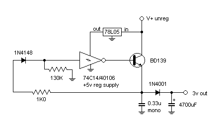
Simple switching regulator (experimental)
Tuesday 21st March 2000
This is an experimental circuit which rapidly "chops" a steady DC input voltage to produce a lower output voltage. Regulation is a function of the chopping - it is caused by the output transistor switching on and off around the target voltage, which when smoothed provides a constant DC output.
Motivation
I've recently become interested in solar energy, so I have also become interested in more efficient ways of regulating a voltage, for example powering a 6v radio off a 12-15v battery. Dropping from 15v to 6v at 100mA with a linear series regulator dissipates (WASTES!) quite a bit of power, which is given off as heat. Because the "chopping" function only switches the output transistor hard on or hard off, very little energy is wasted within the transistor.
I also wanted to be able to keep it simple, plus use standard parts to make it easy to replicate.

The 74C14/40106 schmitt trigger inverter is powered through a 78L05 +5v series regulator (oops! but it's only a small current) so that the input switching points remain constant regardless of the input voltage. A schmitt trigger input typically switches ON at 2/3rds the supply voltage, and OFF at 1/3rd the supply voltage. For a 5v supply the on and off points are about 3.2v and 1.6v respectively. This wide "window" does cause some problems because the output needs to swing between these two voltages. The 1N4001 diode provides isolation from the regulator and the 4700uF capacitor provides smoothing to closely approximate a steady DC voltage. In practice the +/- 0.8v ripple is smoothed by the 4700uF capacitor, but under heavy loading this ripple will become apparent.
Let's follow a single cycle. Say the input to the schmitt trigger is 0v. The output will be HIGH, switching on the transistor and providing almost the full supply voltage across the 0.33uF capacitor. As the voltage rapidly rises, the schmitt trigger switches and the output goes LOW, switching off the transistor. The output voltage rapidly falls again until it reaches the lower switch point of the schmitt trigger and the whole cycle repeats again. If you stuck a 'scope on the non ground side of the 0.33uF capacitor you would probably see something approximating a square wave with rounded edges. The duty cycle with no load should be related to the ratio of input:output voltage (eg 12:3 = 25% on, 75% off). At the 4700uF capacitor you should see nearly pure DC.
The 1N4148 diode can be replaced with a zener diode to give a greater voltage drop (and thus higher output voltage). This circuit outputs around 3v with the components shown.
Conclusion
This is a very simple circuit which was began as a concept and grew onto a breadboard, using parts from the junk box and experimenting with different variations. The original circuit had no 78L05 regulator so while the output voltage was dropped and relatively stable, it varied with the input voltage. The 1N4001 diode was added to the output to isolate the switching function from the large value smoothing capacitor. Try this simple experiment: place an LED with a 1k series resistor on the output, and short out the diode. You'll be able to see the output rising and falling slowly, because the capacitor takes time to charge and discharge.
There are many improvements which can be made to this circuit, it's only the start.
Here's my email (spam cladded) - rowanWEB@sensation.net.au