DC-DC converter to step up input voltage
Saturday 12th February 2000
This is a simple circuit which outputs a voltage which is more than the input. This could be used to power 12v or 9v devices from a 6v system, or even 6v devices from a 1.5v battery (see below).
For some theory and to see where I got the original idea, have a look at Oscar den Uijl's DC-DC converter: http://www.xs4all.nl/~odu/dcdc.html
This circuit uses bog standard parts, without requiring a magical "do-it-all" IC. You can make an ultra simple 1.5v to 9v regulated stepup converter by using a TL496 IC, a coil and a capacitor, but that's not so much fun if you want to experiment. I've already built a TL496 based circuit so I started doing web searches for something that I could make that would allow more fiddling and a wider range of applications.
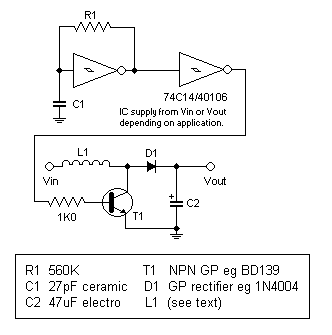
Here is the circuit diagram:

I drew this by hand using MSPaint (yes, I'm a masochist) so some things may look a little out of proportion.
The only unusual component in this circuit is the coil (L1). I am not going to give you instructions on how to wind "the" coil because so many different types work with this circuit. Even a small DC motor works! These are the coils I have tried so far:
- 6v DC motor
- Plain insulated hookup wire on its plastic reel - I managed to find the other end buried in the reel
- 12v DC solenoid from an old floppy drive
- 60 turn coil on ferrite former - robbed from the TL496 9v circuit
The 60 turn coil gave the highest output voltage but the current draw without any load was already 40mA, probably because its DC resistance is very low. The motor and hookup wire coil gave reasonable performance. The solenoid seemed to give the best overall performance.
The values shown for R1 and C1 will cause oscillation at about 40KHz. You should experiment with these too as different coils may perform differently at different frequencies. When I decreased R1 to 130k the frequency increased to about 180KHz and the output voltage increased by a few more volts.
Make sure C2 is rated for the output voltage. I used a 47uF 50v electro because it's what I happened to have lying around. A higher value may give better performance with less ripple on the output.
Input voltage versus output voltage
The first setup of this circuit used the solenoid and a 9v battery. The output was around 41v with no load. With the 60 turn coil, it exceeded 80v! (With a 50v rated capacitor for C2 I didn't leave this running for long...)
What I found more interesting was using a single AA cell (1.5v). You may get mixed results because the 74C14/40106 schmitt trigger inverter may not be able to work at voltages this low. One trick you can do is to power the 74C14/40106 from the output voltage. The only problem is that the circuit needs a kick start, since it can't step up voltage until the oscillator is running. I found that a 10k resistor across the diode (normally 0.6v drop) provided sufficient voltage to get the oscillator started, without affecting the output too much. Startup is not instantaneous because the output capacitor needs to charge. Another way to get it started is to temporarily connect a 3-9v battery in series with a 10k resistor to the supply rails of the 74C14/40106. This method is more reliable but it's not so practical since you need another power source. However, if you are using this circuit to do something like charge a 6v battery from a 1.5v solar cell, then you can simply power the 74C14/40106 from the battery.
Output stability and regulation
There is none. The output voltage will dip as you load it more. While you can use a series regulator such as a 7812 or 7805 on the output (take care not to exceed their maximum input voltage) I'm guessing that pulse width modulation (PWM) of the 40KHz square wave would be a more efficient method of regulation. I haven't looked into this yet as it adds more complexity to the circuit, requiring some sort of feedback to vary the duty cycle. A PIC or Atmel with an A/D converter and a spare output, plus some fancy programming, would probably do the trick.
Conclusion
This is a basic circuit only and it can be improved in many ways. Building it on a breadboard makes it easy to fiddle with values of components. Make sure you don't accidentally exceed the ratings of any components if you manage to find a variation that steps up 12v by 10 times!
Note added September 2009 - I get a lot of emails from people asking for detailed help with modifying this circuit. I'm not an engineer - my knowledge of electronics is elementary to intermediate. In addition, I haven't fiddled with this circuit for nearly 10 years (this article was written in early 2000) so I cannot offer any further assistance beyond the text of this page. Thanks and apologies for any inconvenience.