
Simple switching regulator (experimental)
Thursday 20th April 2000
STOP PRESS
After some further tests I've found a major problem with this circuit, it appears there is either a fault or it's acting more like a plain old linear regulator, because the BD139 transistor is getting hot and the circuit is drawing 150mA+ from a 12VDC source when powering a nominal 150mA 6VDC load. (It should ideally be drawing about 75-90mA from the 12VDC source). There probably needs to be some hysteresis added to make the comparator output more "snappy". The circuit is still oscillating but it's likely it is not generating a nice clean square wave with sharp edges at the base of the BD139. That will teach me to fiddle at 3:30am... (End stop press.)
This is another version of the DC switching regulator (Mk I) which also rapidly "chops" a steady DC input voltage to produce a lower smoothed and averaged output voltage. The advantage of switching is the efficiency is much higher, since the dropped voltage is not simply wasted as heat.
This version is even more simple, with only 6 parts for the basic circuit. It should also have less ripple on the output under higher loads, although I have not been able to test this. Here is the circuit:
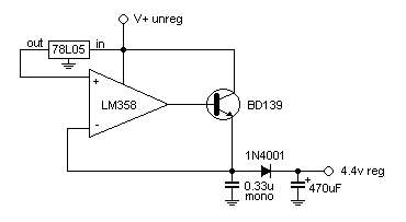
This circuit uses a standard 78L05 low power 5v regulator in a novel way - as a voltage reference to a comparator. When the output voltage is LOWER than 5v, the output of the comparator switches high, turning on the transistor. The output voltage rapidly rises and once it is HIGHER than 5v, the output of the comparator switches low, turning off the transistor. The 0.33uF mono capacitor provides some smoothing and prevents oscillation in the multi-megahertz region. Under no load this circuit oscillates at about 32KHz. The diode and 470uF electro provide isolation and extra smoothing to produce an almost pure DC output.
Note that the output is slightly lower than the reference voltage because of the inline diode. This can be solved by jacking up the output voltage of the 78L05 regulator by adding a diode inline with ground. Another way (untested) is to add a diode inline with the return path from the 0.33uF and the negative input of the comparator, so that the voltage on the non ground side of the 0.33uF capacitor stays around 5.6v (when using 1N4001 diodes with 0.6v forward drop).
If your load is small or not too fussy about ripple then you may be able to remove the diode and 470uF capacitor completely, and take the output directly from the non ground side of the 0.33uF capacitor. You can also experiment with values of the bypass capacitor - I used 470uF because it's what I happened to have at the time. You shouldn't need the huge bypass capacitor that the first version of this circuit did because the output ripple is much lower, the comparator causes the transistor output to "hunt" around 5v rather than swinging between 1.6v-3.2v as the first version does.
Other 78Lxx devices and even 78xx devices should work in this circuit without modification. Take care not to exceed the input voltage for the regulators. I am not sure what the supply limit for the LM358 is.
Again this is just a basic circuit that started as a concept in my head and happened to work on the breadboard. I hope you can make some use of it, and perhaps improve it. If you do, or have any suggestions, I'd like to hear from you.
Here's my email (spam cladded) - rowanWEB@sensation.net.au